Servo Tester
Notes about different experiments with servo motors.
Software
While building BOB-303 robot had to make sure servo motors are in the right initial 90° position before mounting so I've created Arduino program to test and set servo motors angle.
Theory
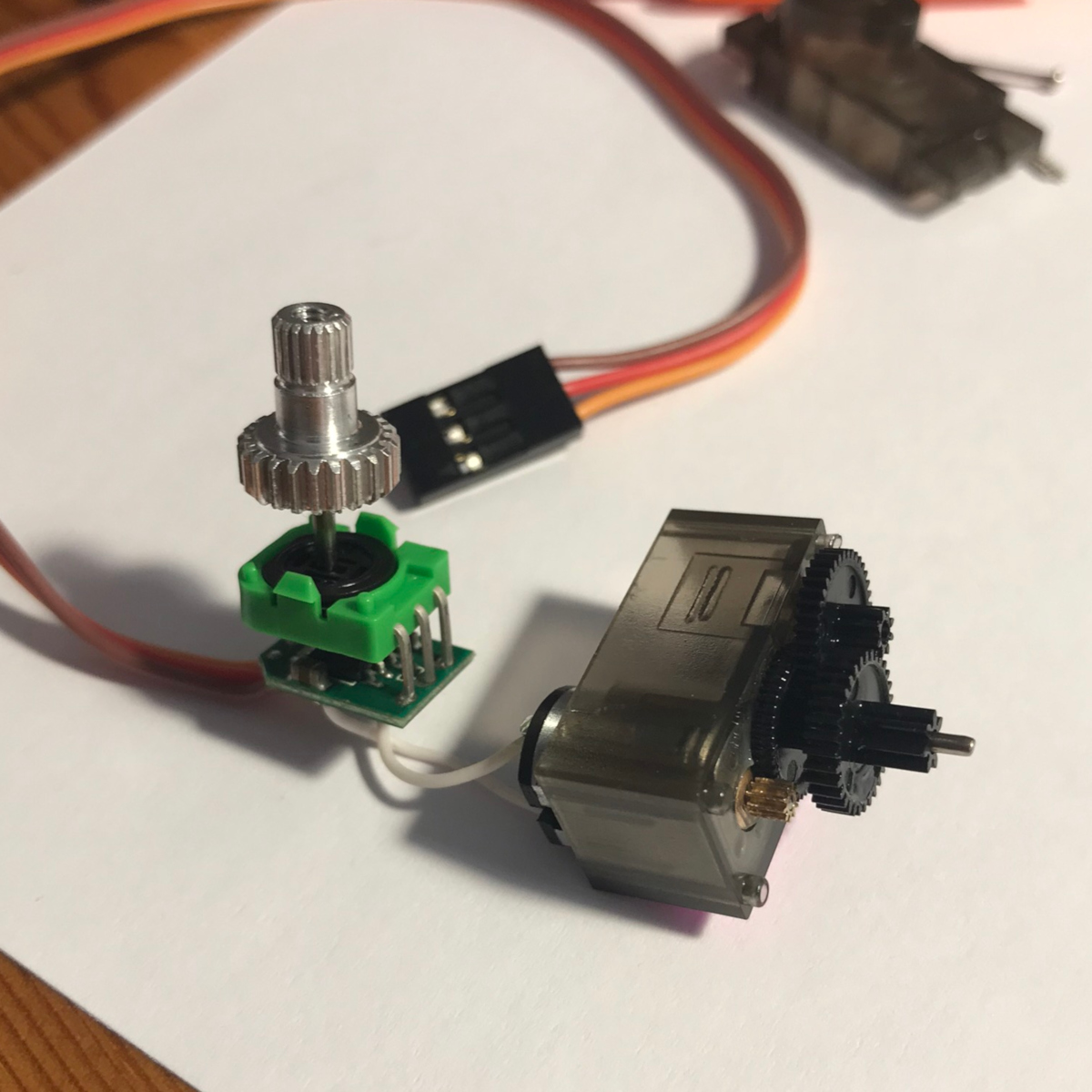
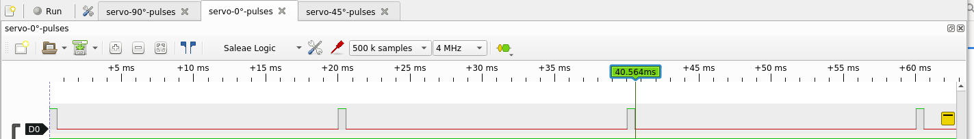
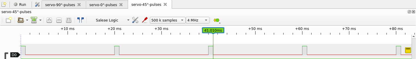
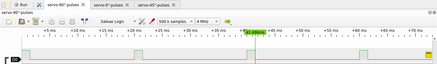
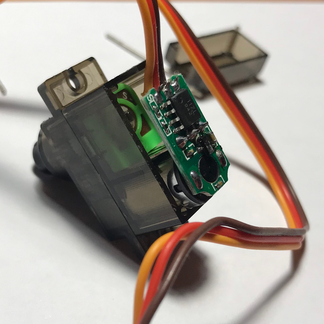
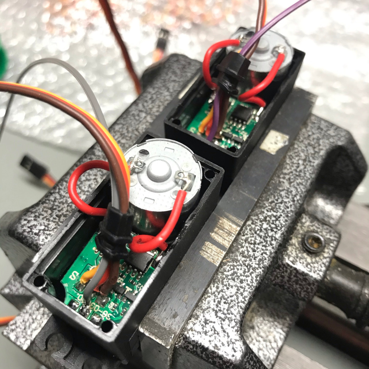
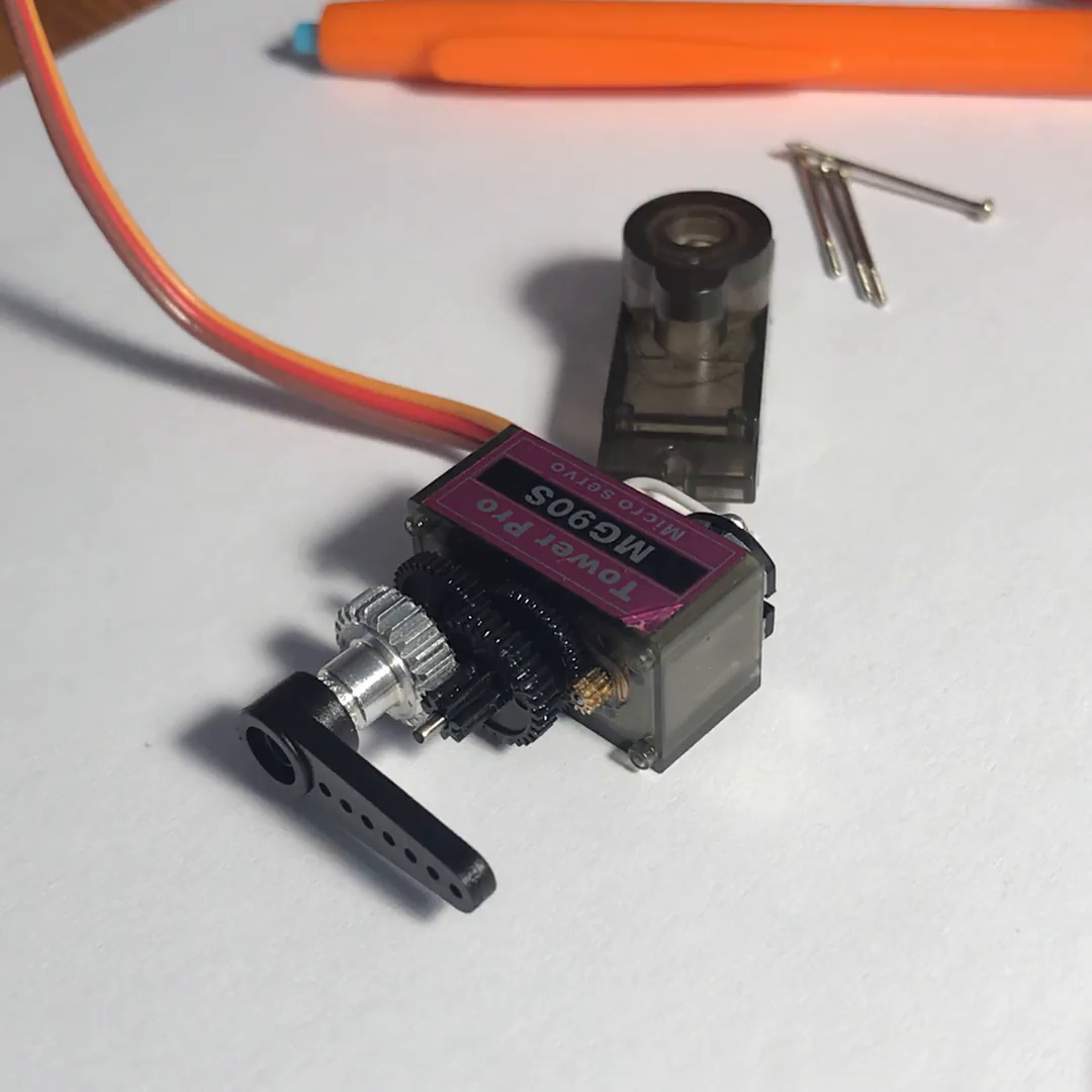
Inspired by this video I've also disassembled one servo and measured the the PWM Pulses controlling the angle. They are 20ms time-slots and the width of the pulse at the beginning instructs the servo electronic about the desired angle. On the first picture you can see the green feedback potentiometer that is responsible for servo adjustments. There is a DC motor and controlling chip in the plastic box on the right from it.
Turning servo into DC motor
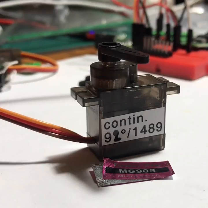
That video was right, by removing potentiometer and adding two 1k resistors instead, it's possible to turn servo into a DC motor. Finding a "stop point" may be different from servo to servo. In my case it was 1489μs.
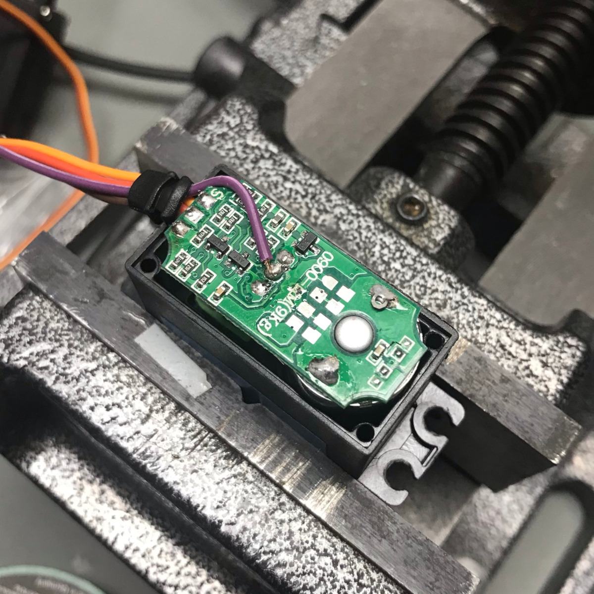
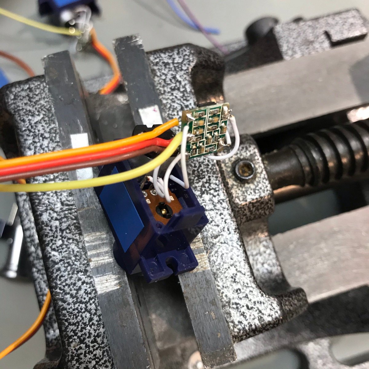
Adding position sense wire
Soldered one more wire to the middle pin of potentiometer voltage divider
and by that having 4th pin with analog voltage equal
to servo tilt. In my test case:
0° → 0.305V
90° → 1.491V
180° → 2.681V


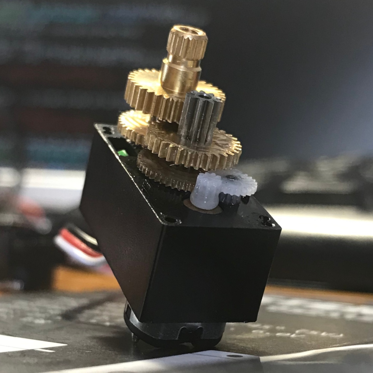
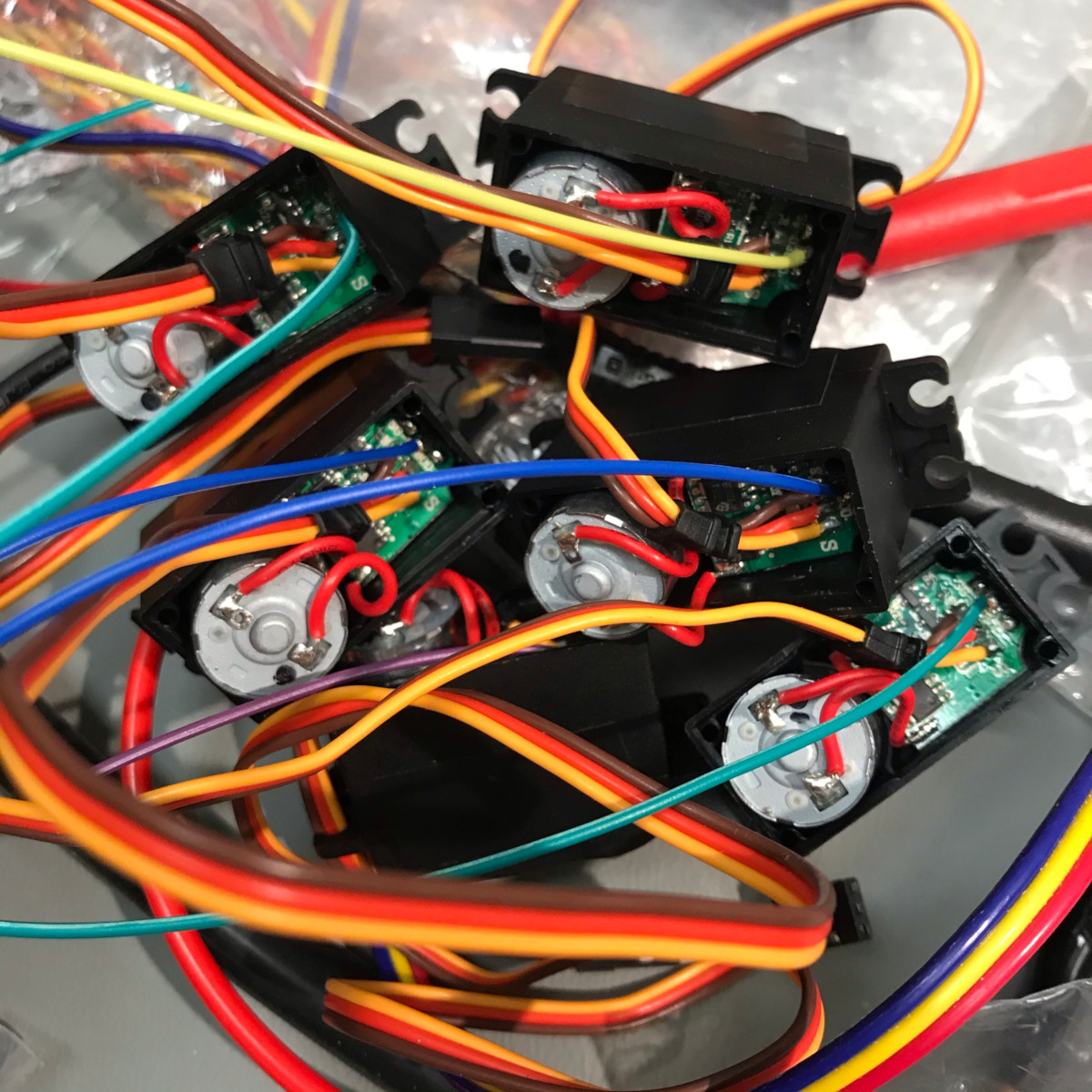
Opening "Metallgetriebe" servos
Ordered servos from reichelt claiming to have metal gears. Most of them did, but the last two little ones:
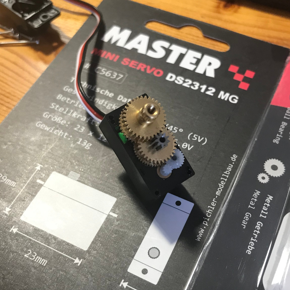
Opening "metal gear" servos
Ordered servos from aliexpress claiming to have metal gears. Same as the first servos, but this time the plastic gears where made in grey (not black) plastic so it's not so obvious wrong without opening:
Soldered one more wire also to this one:
0° → 0.355
90° → 1.677V
180° → 2.947V

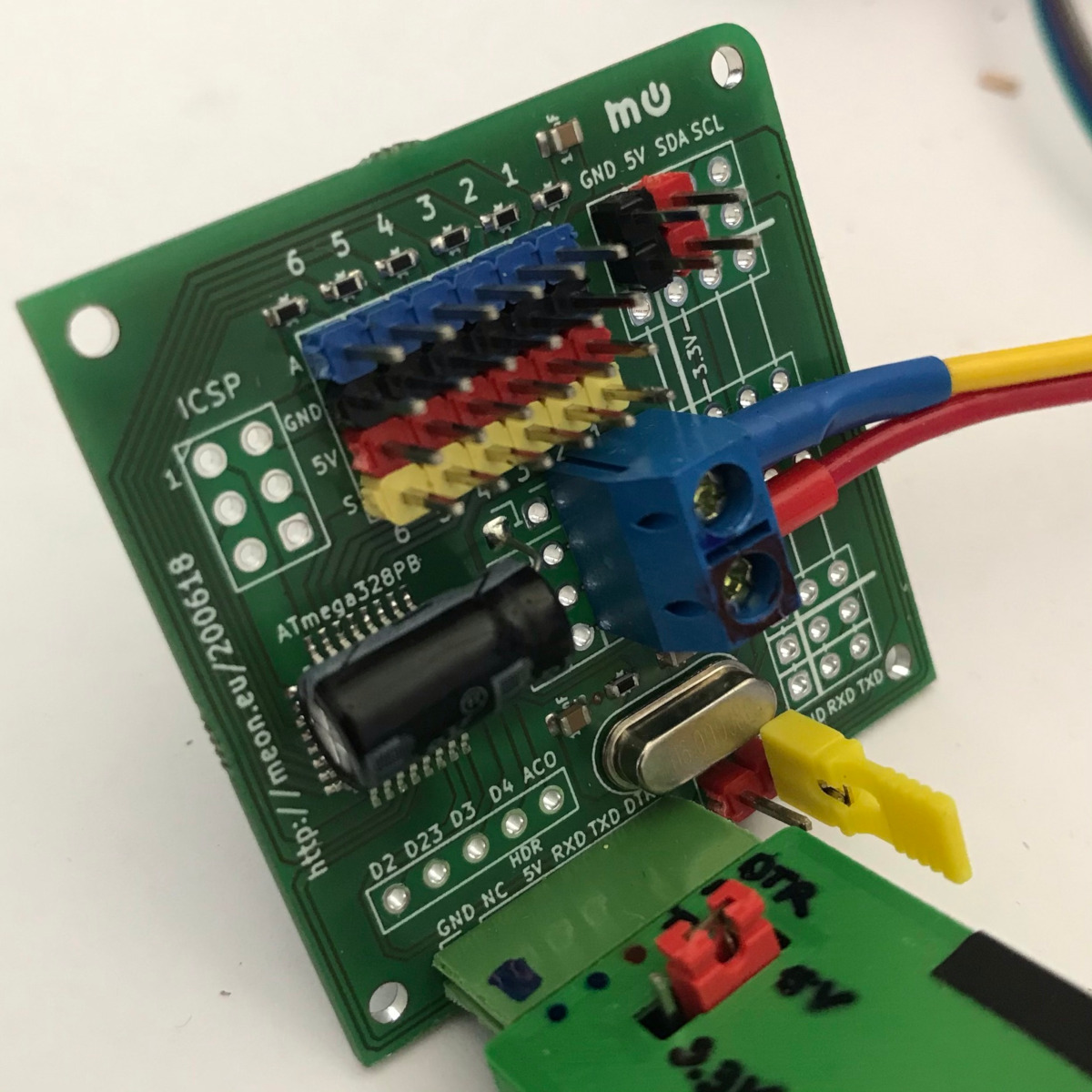
TODO
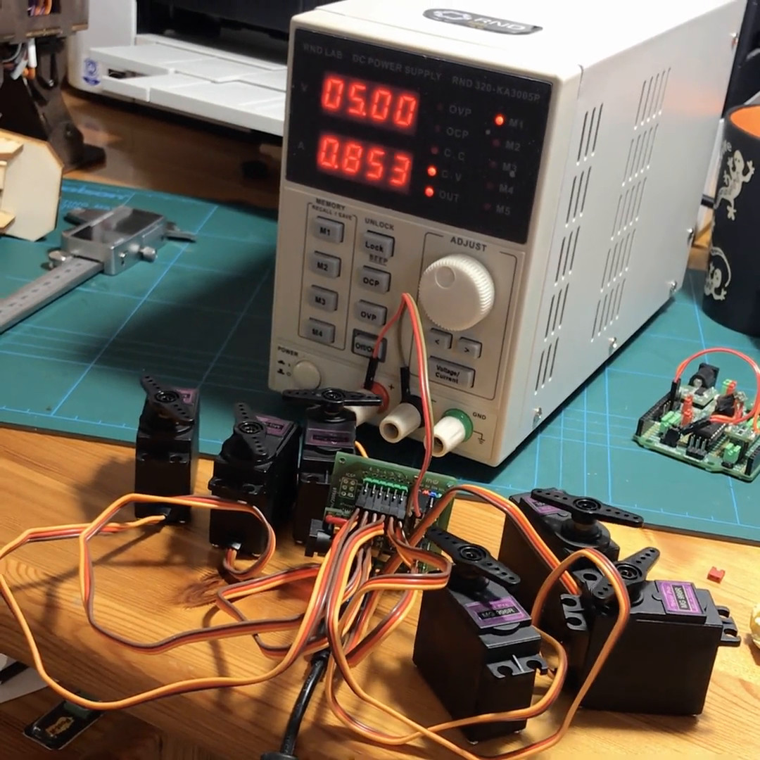
design and program fully test board to attach 6 servos and run/control them at once.