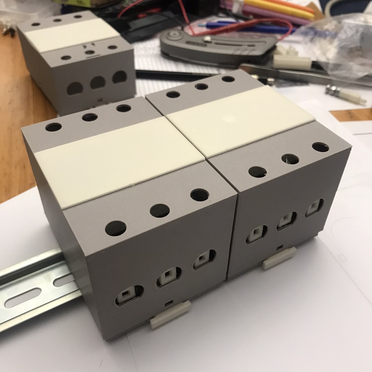
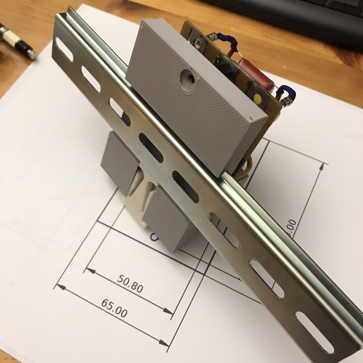
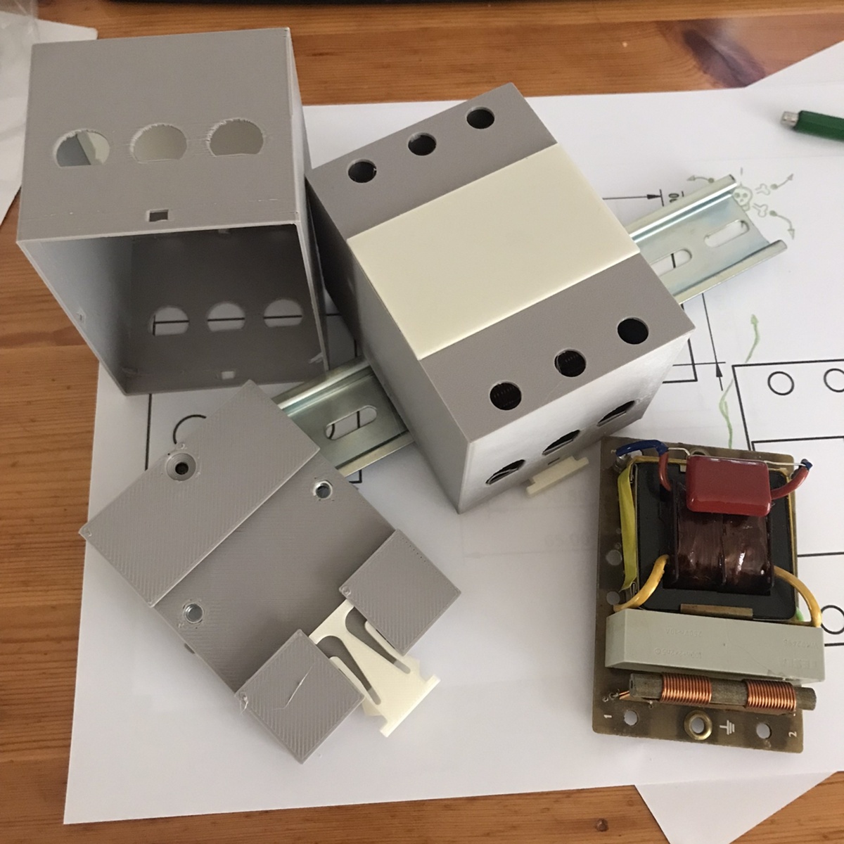
3D printed din-rail box with click lock
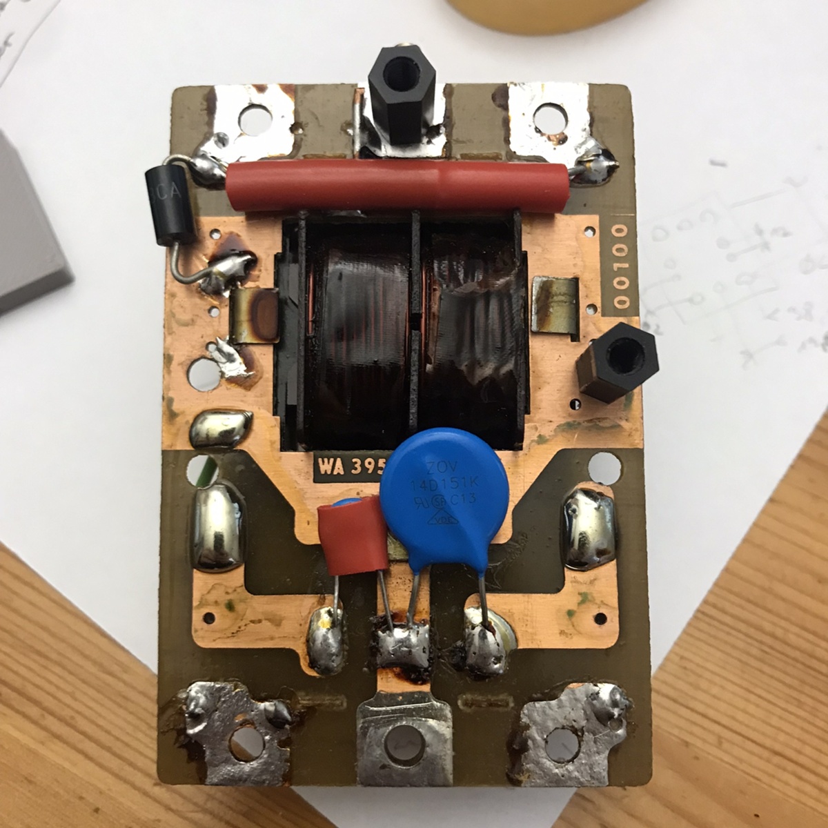
Got an input filter for solar panels ready made on pcb, now the question was how to fix it into the electrical box. The common mechanical element used is din-rail. The challenge was how to fix this pcb on to it. Here's my make.
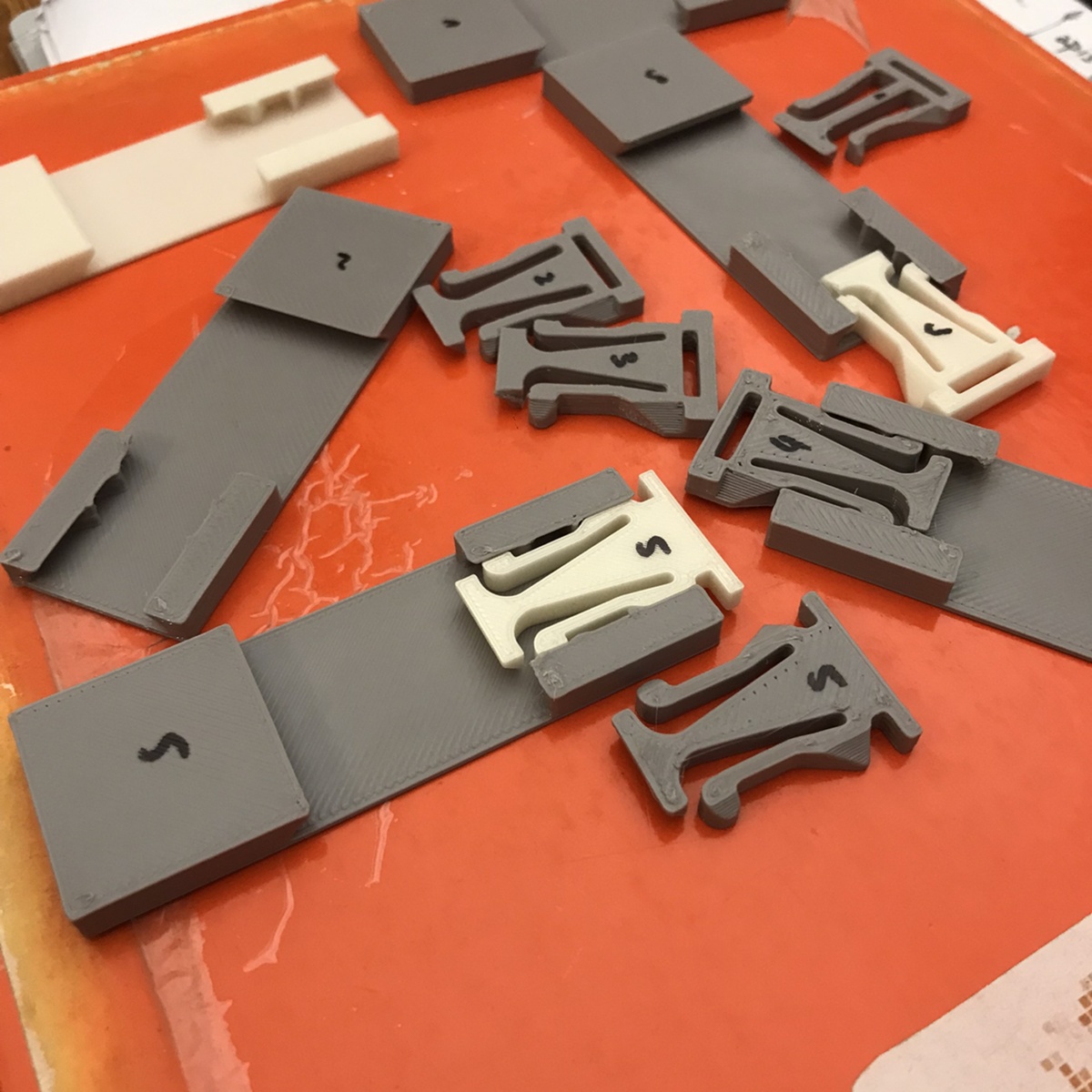
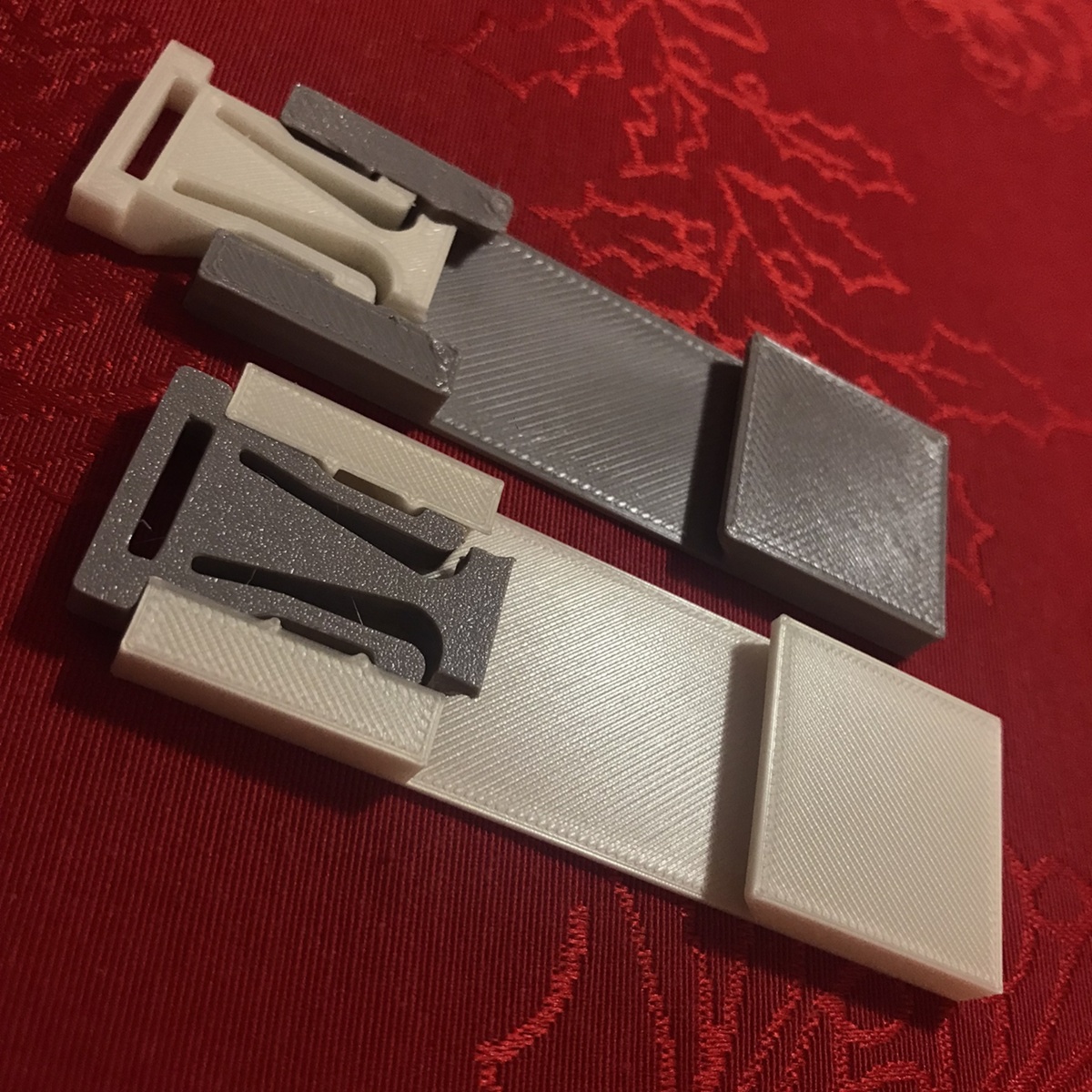
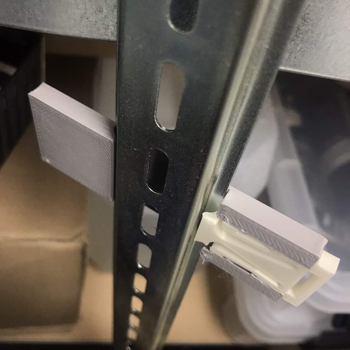
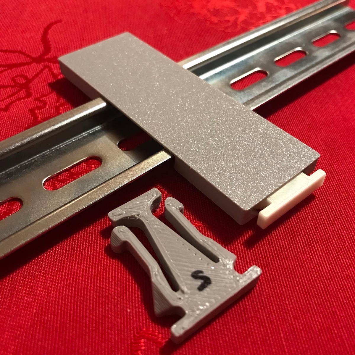
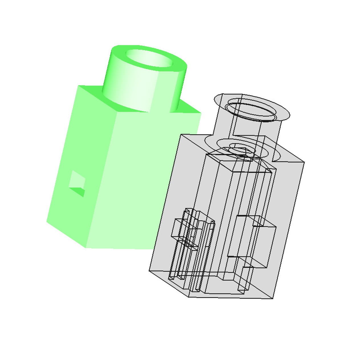
click-lock
I've checked couple of fuse box elements that I had around for inspiration and found out that they all have different kinds of locking mechanisms. Most of them click-lock in place, one even totally without moving parts only with a single spring.
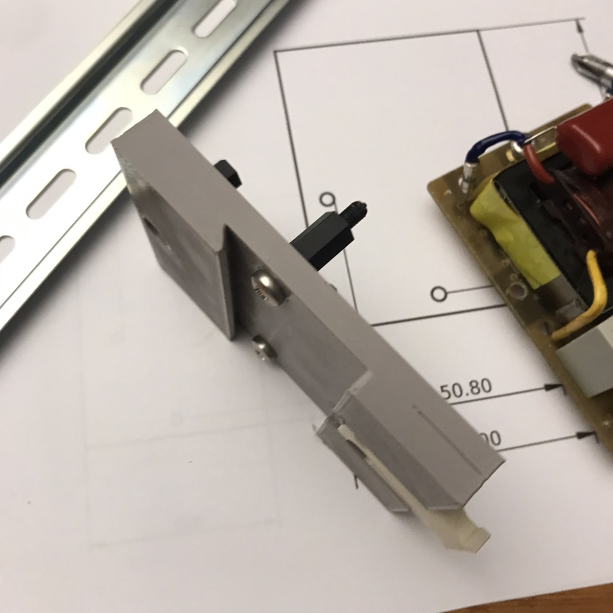
After couple of tries, I was able to lock a plastic block on to the din-rail. Once the moving part is inserted inside, it will snap into two positions - open and locked.
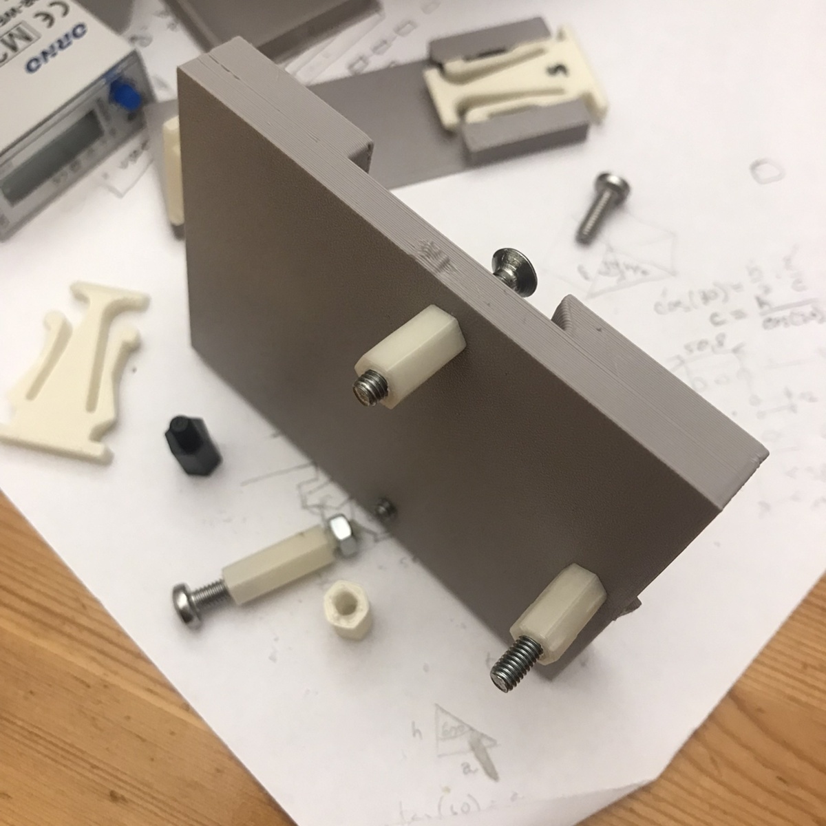
attaching pcb onto the flat plate
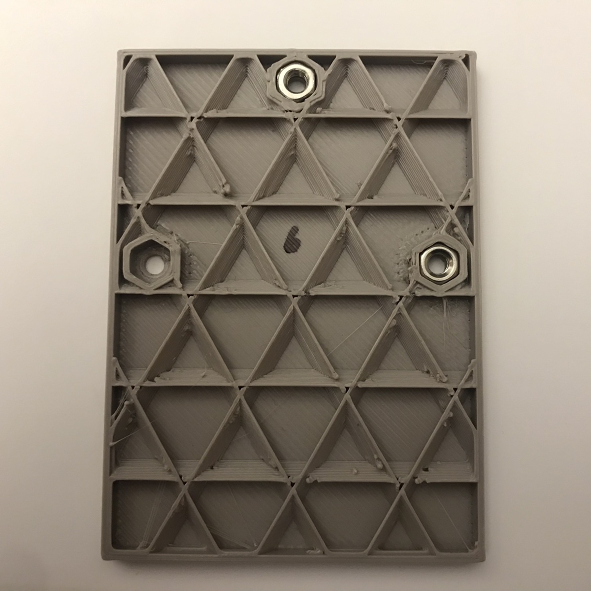
There were M4 holes, spacer, screws and nuts available so I used those. Inside the plastic I've made a special shape that can host a nut and/or can have screw going through it. This allowed for screwing spacer both directions - with pin into a nut or with hole using screw. The latter was needed because the holes on the pcb on the sides did not allow for nut/screw turning around, they were too close to the wall of transformer. So the nut had to be put on the pcb hole hole, then spacer with pin up screwed into it and then the spacer attached with screw from the bottom of the plastic plate. In the middle the spacer pin could go directly into the nut hidden inside plastic and then pcb be fixed with a screw into it - the common way how to do this.
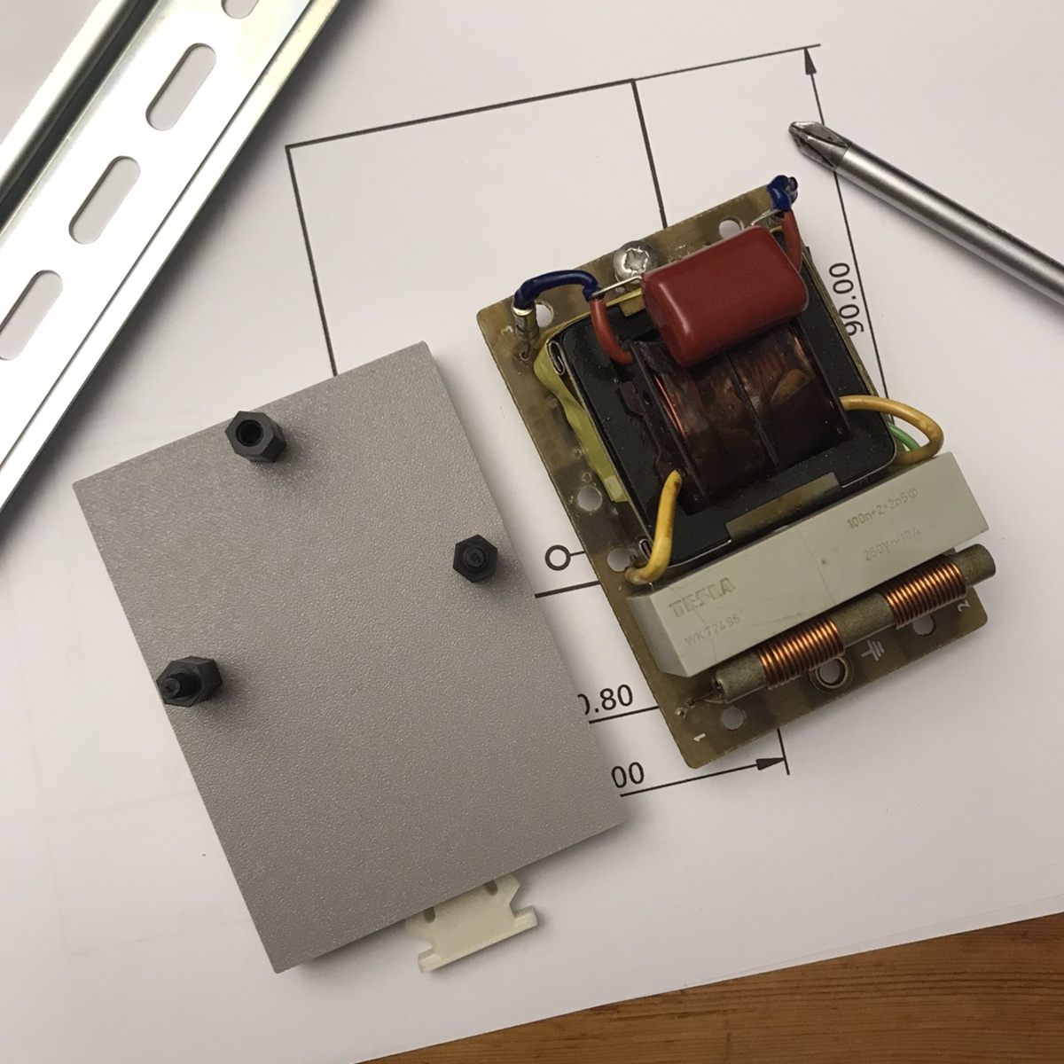
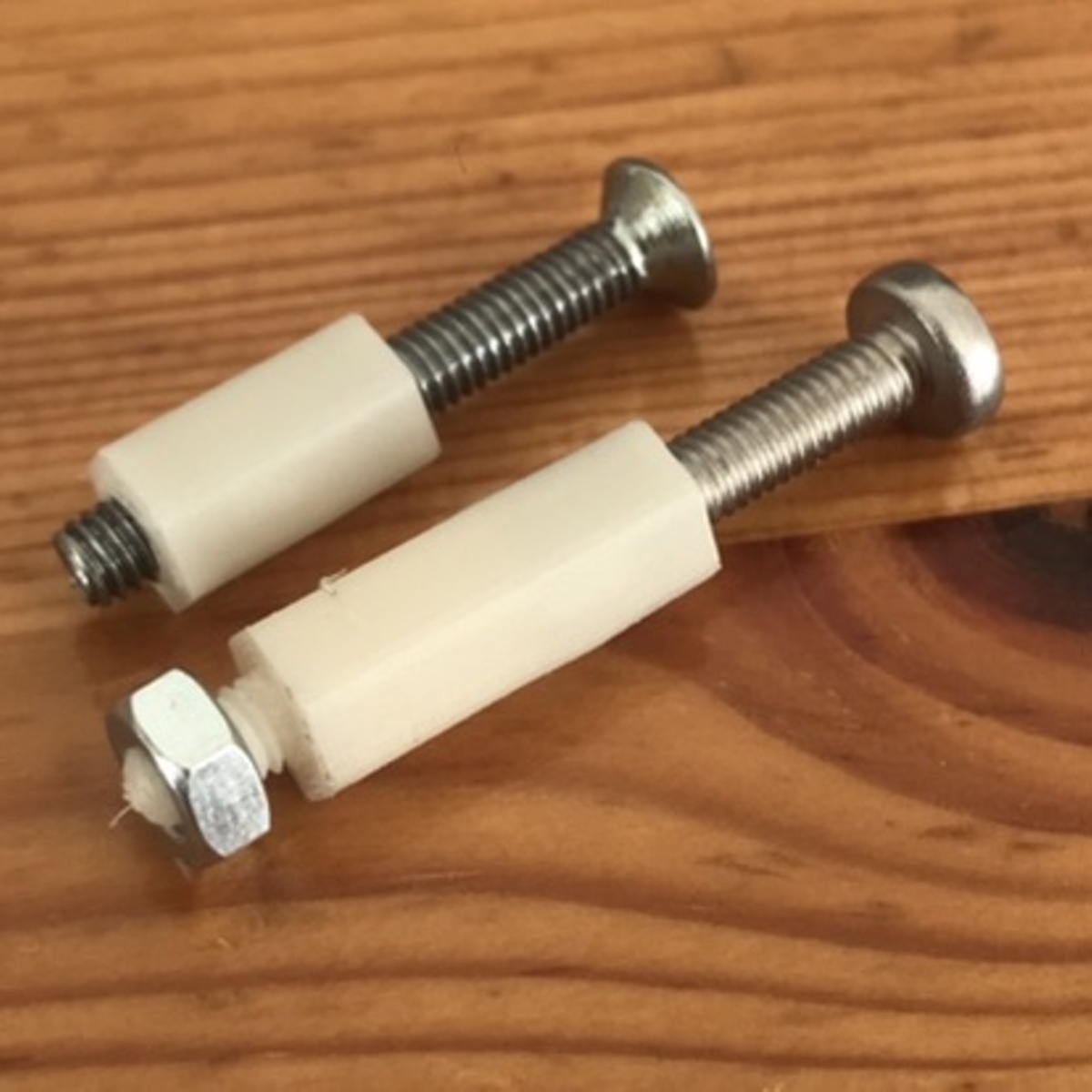
spacers
At some point I've realized that I have only 4 spacers (black on the pictures), but two pcb and 6 holes to attach. Shopping for M4 spacers would take some time, so I've tried to 3D print some instead and cut thread into them with a good success (white on the pictures). The 3D printed middle spacer was of a new kind - only with a hole through where I've cut thread inside and used screw with countersunk head.

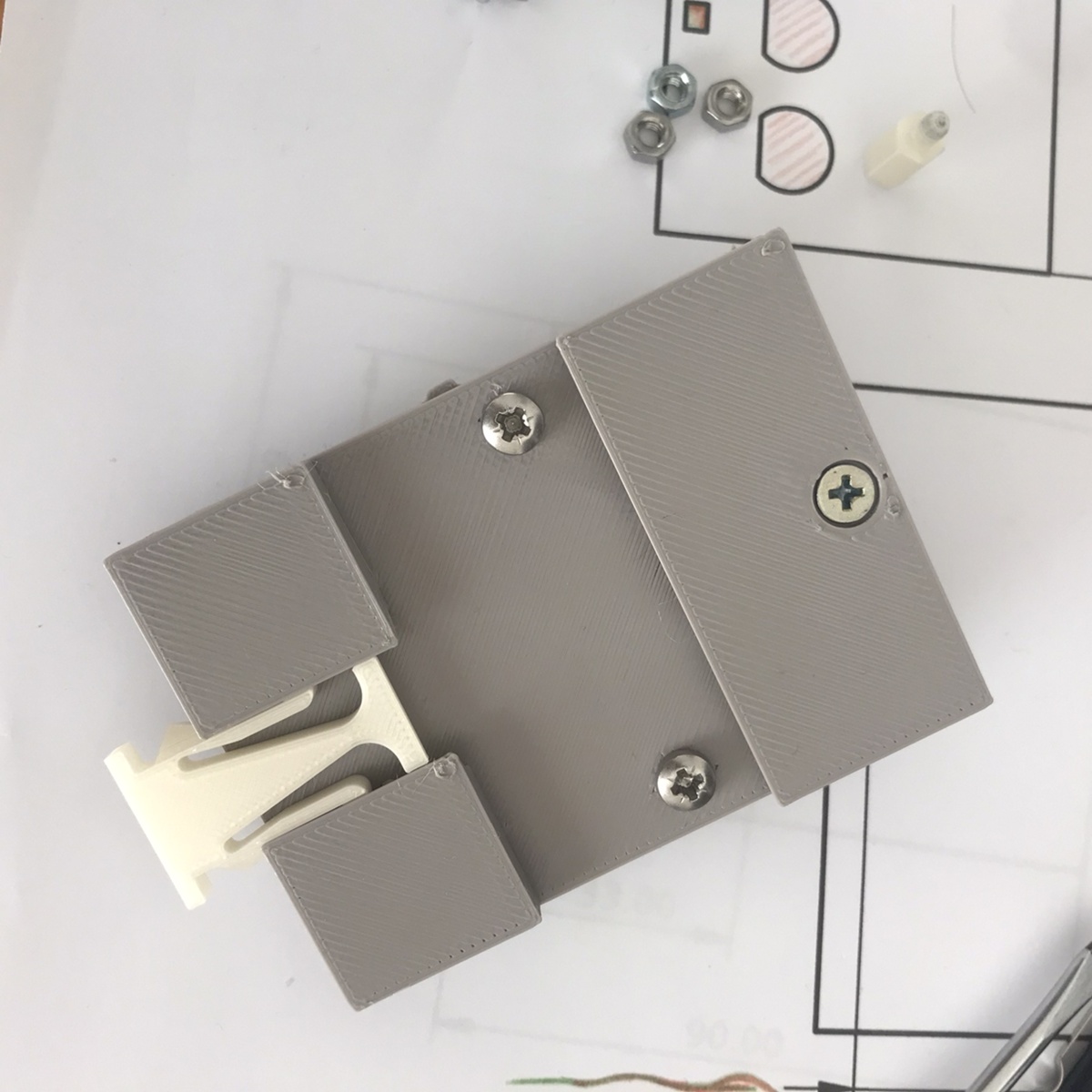
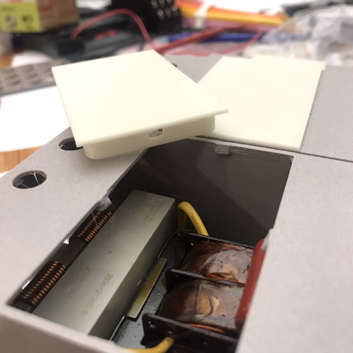
top cover with window
To cover the whole think, I've printed a top box which is attached to the bottom with three little notches. I could have printed the box on the top whole, but I've created a window for the future purpose of attaching there different kind of boxes then just a current flat surface. This is how the common electrical din-rail boxes look like - with small middle box on the main body.


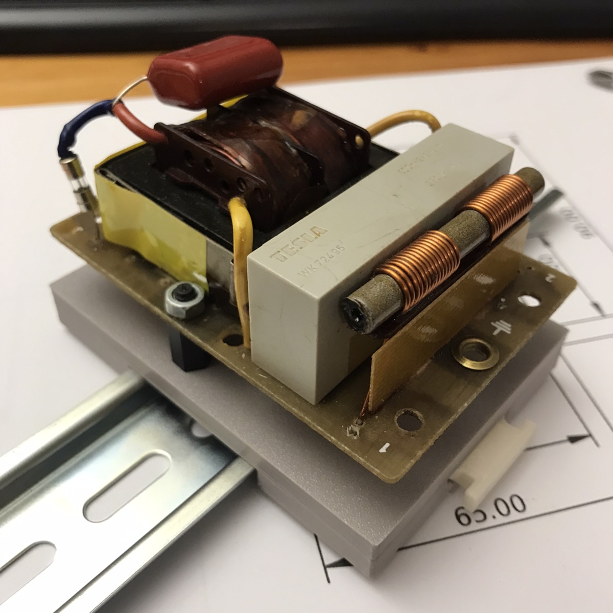
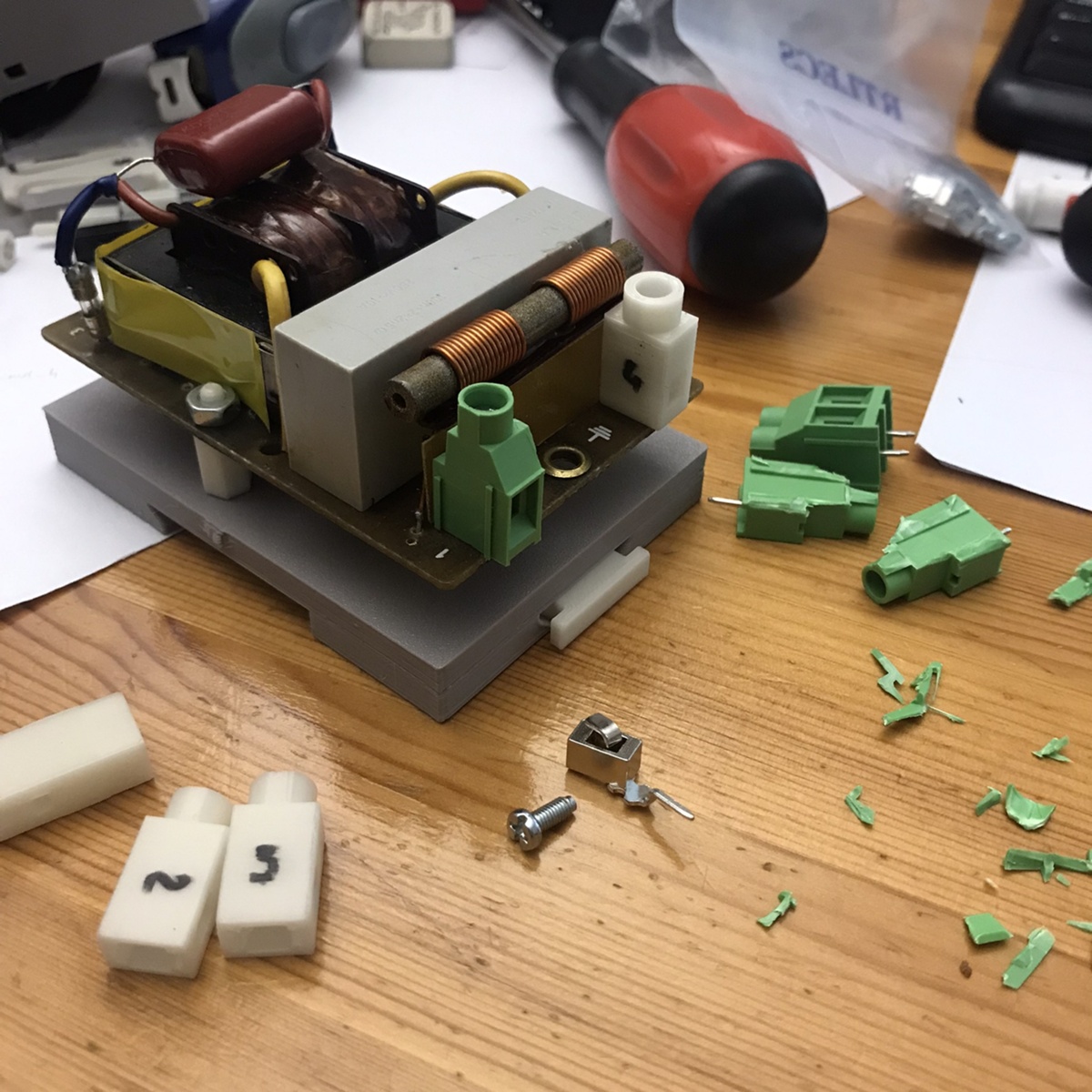
terminal connectors
And the last thing to solve were the terminal connectors. I wasn't able to find any terminal connectors with a screw that were just as single ones. Only two and three. So I've disassembled them, learned the mechanism and printed new body. I've realised that I could have just cut the three screw terminal ones in the middle to get two single terminals, but hey if you have a 3D printer you print everything, right?
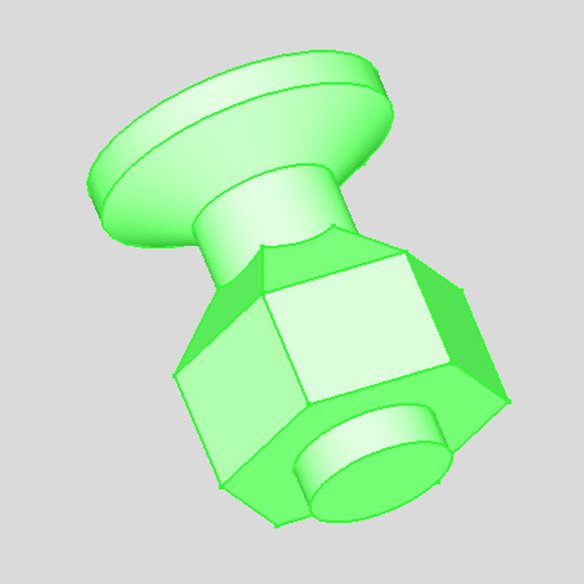
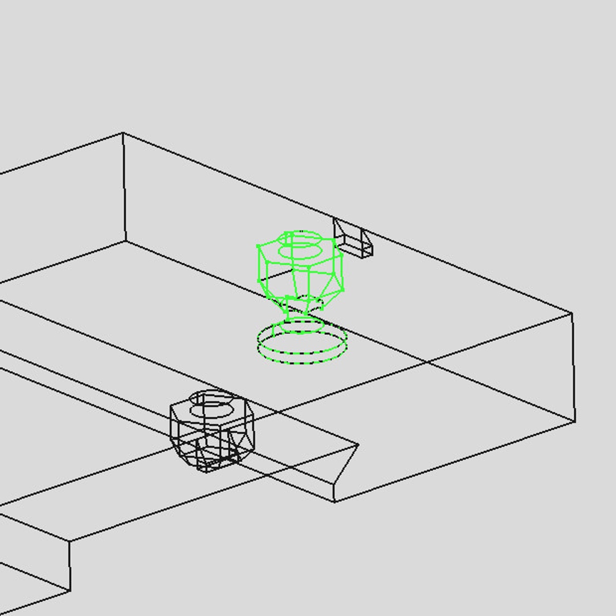
There was a little trick the "professional" terminal connectors use, that I was able to reproduce with 3D printing too and that is that once the screw is inserted into the tunnel/shaft on the top, it can freely move up and down, but can not drop out and will stay there unless force is used from bottom to get it out. This can come in handy with electrical designs so that the screws can never accidentally get loose and drop up into the electronics.
I was also able to print the top round hole in the middle by supporting it with 45° square loft coming from the walls.
The whole thing is on the limit of what detail can be printed with 0.4mm nozzle.


and voi là!
Two completely non-standard unique electrical boxes...